I’ve previously mentioned that I wanted to upgrade my heating system so I could program it with more complex timings or control it form my phone. But there’s a catch: The house is rented, so the whole system must do no damage, be made only of removable parts and be installed without modifying any of the existing infrastructure.
In this post, I’ll talk about how I managed it, how it works and what the current state of the project is.
Background
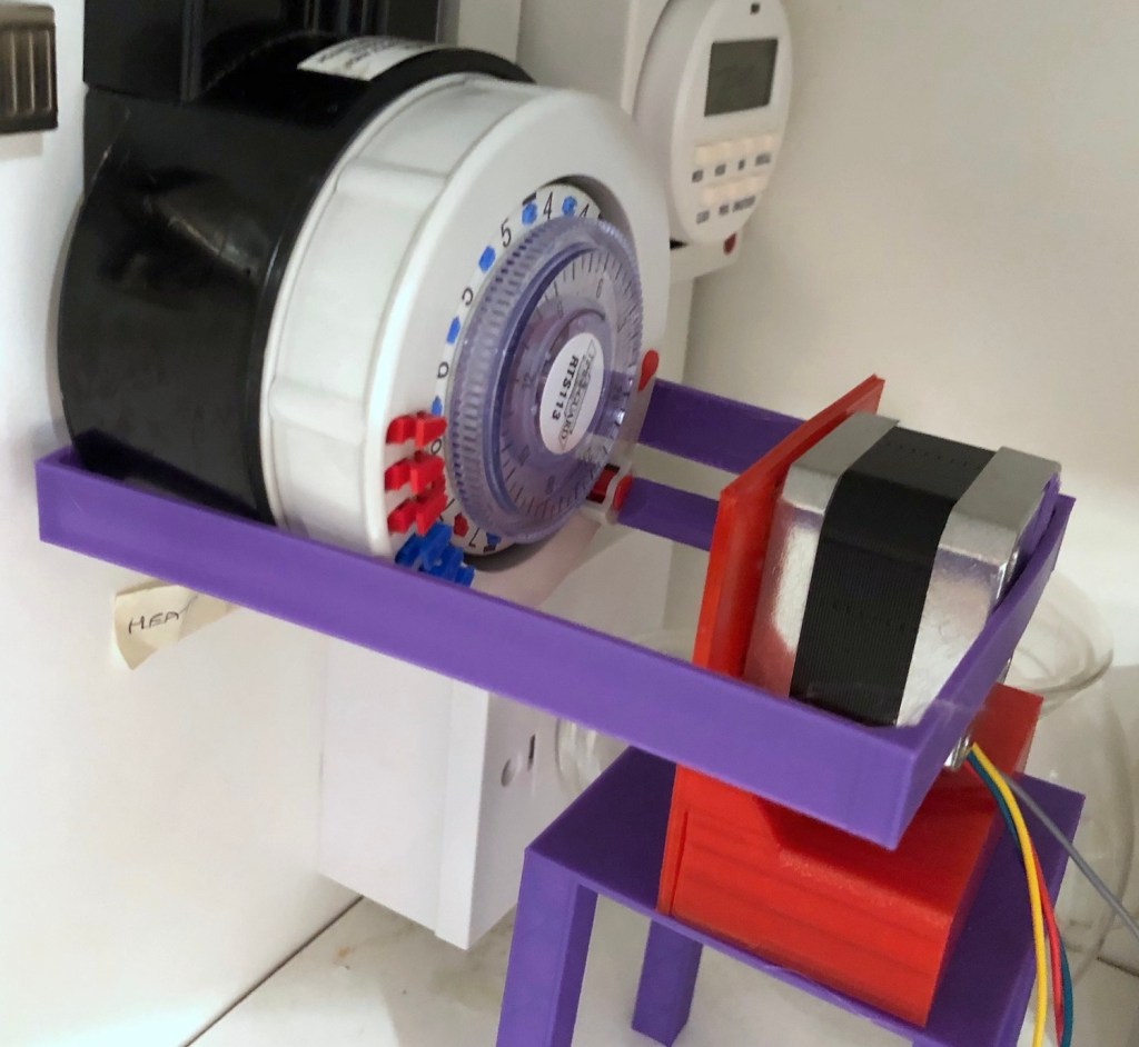
My electric heating is controlled by a Timeguard RTS113 mechanical timer located awkwardly in a kitchen cupboard; it consists of a large outer ring that rotates once every 24 hours. On this ring, you push in red (on) or blue (off) plastic pegs (called tappets in the user manual) at the time you want the heating to turn on or off. As the peg passes a control spindle (representing the current time in the bottom right) it pushes it around approximately one eighth of a turn. Each eighth of a turn of the control spindle, toggles the heating on or off.

A second inner ring allows you to suppress the morning or afternoon schedule for a given day in the week. For example, you can have the heating come on at 6:00am and 7:00pm every day, except on Saturdays where it does not come on at 6:00am because the morning schedule is suppressed.
This works reasonably well, but it’s not very flexible – you pretty much a to live your life on the same schedule every day – if you deviate from it the heating is either wasting power while you’re out, or you’re freezing and have to reach into the cupboard to press the override button.
I’d love to have a smart thermostat such as Nest or Hive but they don’t support my electric heating and as this is a rental house, I’m not able to modify anything to support them.
What I Wanted To Do
The control spindle that is rotated by the pegs has a small slot on the top that can be turned manually using a screw driver to toggle the heating on an off. I can remove all of the pegs and use a stepper motor to very gently turn the spindle each time I want to change the heating state. I could then connect this to a controller that receives instructions from the internet, and write whatever software I wanted to run the schedule.
The Motor
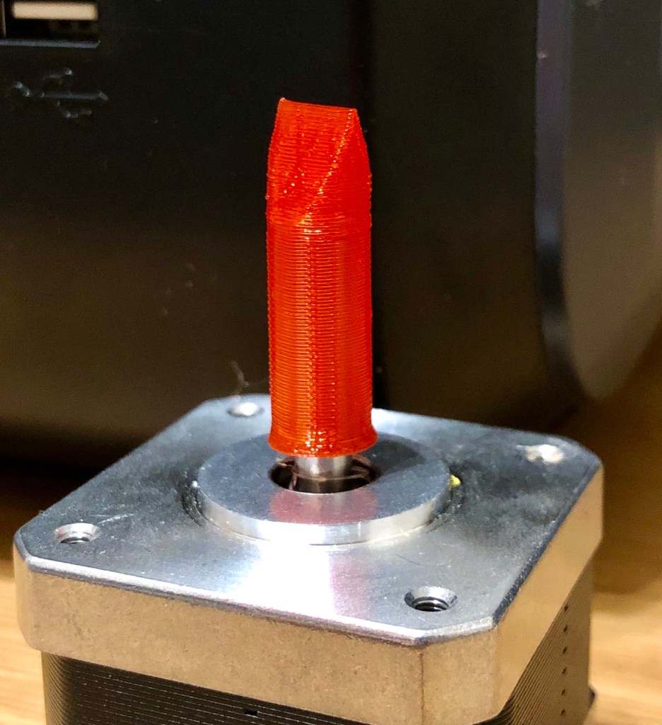
The first challenge I tackled was figuring out how to get a motor to actually turn the control spindle. I started by picking up a stepper motor and motor controller from the Pi Hut. In my last post I mentioned that I hot glued a metal washer to the motor shaft as a successful proof of concept. Now I had to design something more sturdy.
I used Tinkercad to design a driver head that would fit over the motor shaft and engage with the slot on the control spindle. Although It took a couple of attempts to get the sizing correct, I 3D printed this and was very happy with my first ever self-designed 3D print.
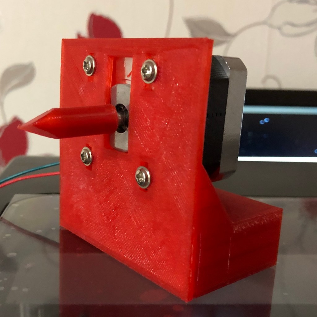
Next, I designed and printed a bracket that would hold the motor in place. I added rectangular slots around the screw holes, so I could adjust the height during install and made sure it had a large solid base so that it was stable and did not tip over.
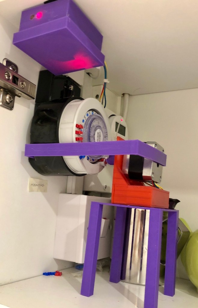
To get this into position, I considered some elaborate brackets that would hang down from the top of the cupboard, but ultimately built something that very much resembles a table. This has the unfortunate effect of taking much more space than I’d hoped, but I thought it best to get it all working before building a more convoluted setup.
I installed this temporarily to see how it worked. It seemed to go well at first, but then encountered a problem: After a few uses, the motor would push back off the spindle and the driver would slip out of the slot.
To fix this, I 3D printed a bracket that would clip onto the back of the timer and hold the motor in place so it cannot push away. This worked great and I haven’t had any issue with it slipping off since. The original driver I printed above was too large and made this bracket too wide for my printer’s print bed, so I re-designed it to be smaller… and now its purple because I changed filament half way through the project.
Hardware
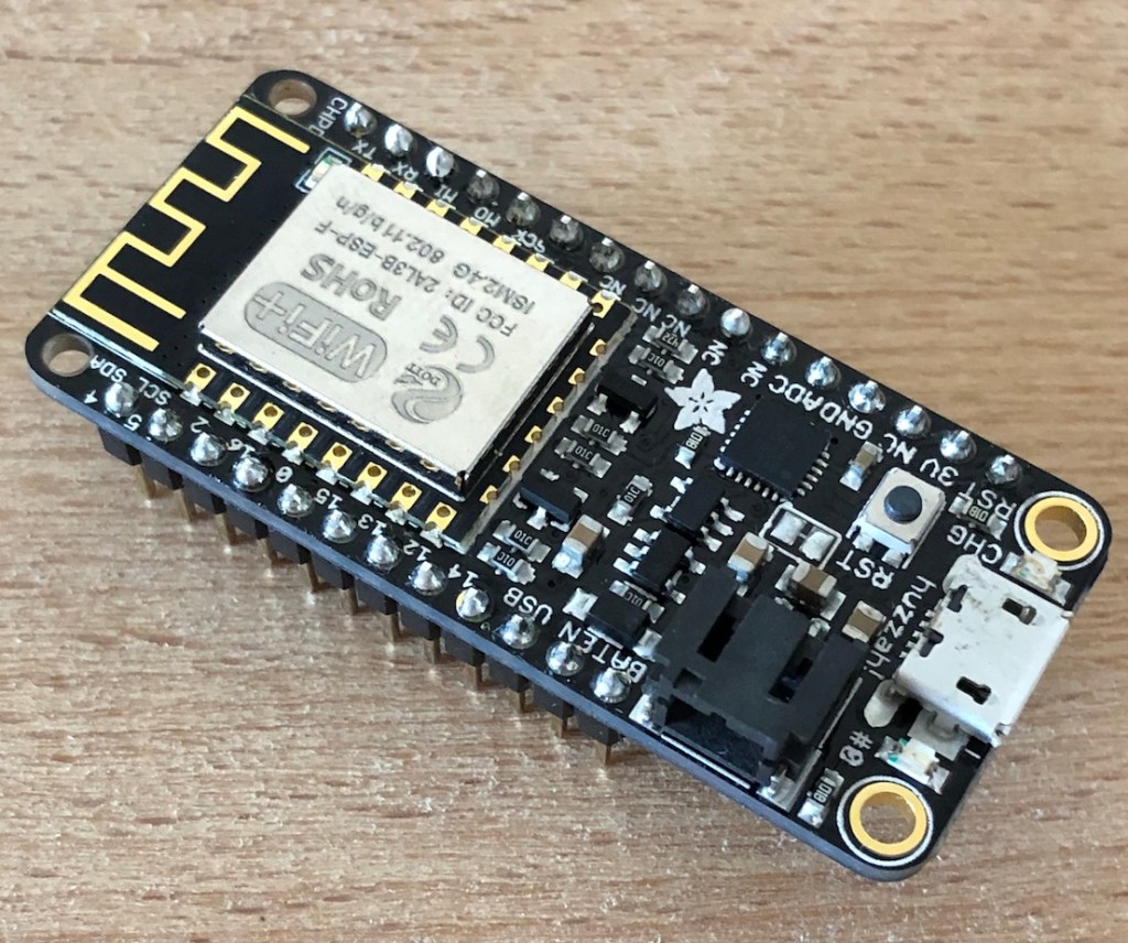
I’d been looking for an excuse to have a play with an Adafruit Feather for a while and this seemed like the perfect opportunity. I opted for Huzzah with ESP8266 – it has loads of input / output, is easy to program using the Arduino IDE and allows connection to my network using Wifi – perfect for this project.
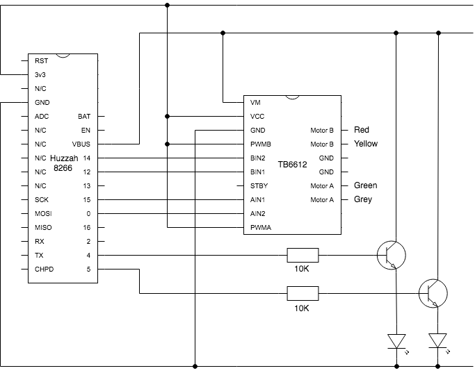
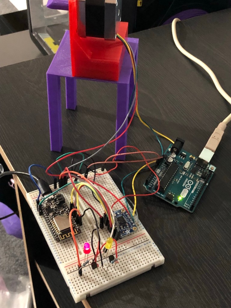
After checking out the pin outs for the Huzzah I put together a schematic of how it would all connect together. As the ESP8266 is all 3.3V logic and the Huzzah has quite a low current limit, I needed to provide a separate power feed to the motor. In early prototypes I used an Arduino as a quick-and-easy power supply (you can see this in the below photo), but on further examination I learned that there is a VBUS pin that is directly connected to the power pin form the USB input so that really simplified it.
I threw all this together on a breadboard to create the below tangle and fitted it up to test.
Software
Having previously been impressed with Adafruit IO in my air quality project, I decided to use it again here. I set up a new “heating” feed that I could write a 1 or 0 in to turn the heating on or off.
I wrote an Arduino sketch that used the Adafruit IO library – using MQTT to subscribe to changes in the heating feed. When the value changes to either a zero or one it rotates the stepper motor sufficiently to turn the heating off or on respectively.
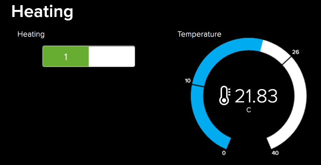
I created an Adafruit IO dashboard with a toggle switch linked to this feed and a display showing the current temperature so I could easily see if it is going up / down (ie. To check if it actually worked).
I discovered early on that the latency on Adafruit IO can be quite high (I’ve seen a message take up to 30 seconds to arrive) and very variable, so debugging the setup was a bit of a pain. For this reason I added two LEDs that show the state that the hardware believes the heating to be in. This way I can tell if the device received the MQTT message yet.
The full Arduino sketch is available on this GitHub Gist.
Bugs, Mistakes and Problems
So far I was amazed that this project as gone as well as it had. I’d gone from a slightly vague idea of “maybe I can turn the timer manually” to actually being able to turn the heating on and off. Along the way, I’d learned an amazing amount about 3D printing and built a bunch of custom parts for it.
But the next main challenge was to make this into something I could rely on; it had to do better than just work – it had to work every time. Perfectly. In pursuit of that aim, I hit a few issues.
Holding Torque
As this was my first time playing with stepper motors, I experimented early on with how far I should rotate the control spindle. Sometimes the motor would be in the wrong position so I would try and manually turn it to the right position, only to find it was locked solid and getting warm.
This seemed like a hardware bug at first, but I learned that its intentional – after a stepper motor is rotated to the desired position, it holds. That is, it continues to energize the coils in its current location to prevent the motor from being moved.
This makes perfect sense for something like a printer, but given my intended use involves moving the motor for less than a second, then leaving it alone for hours at a time I was worried that I might damage it, so I wanted a way to shut it down between usage.
I could fix this in the hardware – the TB6612 motor driver has a standby pin that you can pull low to disable the motor, however to keep it simple I opted to just manually setting the motor output pins to low in the sketch.
digitalWrite(0, 0);
digitalWrite(15, 0);
digitalWrite(12, 0);
digitalWrite(14, 0);
Turning the Motor Enough
The premise of this project is to manually turn a control spindle enough to toggle it on or off. But getting the exact amount to turn it right has been a bit tricky. Sometimes it wasn’t enough, others it was too much and it would turn the heating on and them back off again. Getting this right was pretty much just trial and error. It was a pain.
Software Watchdogs
When first testing the motor with an Arduino everything worked fine, but as soon as I switched over to the Feather I had a problem – every time the motor turned, the whole board would crash and reboot.
After researching it, I learned that the ESP8266 has a software watchdog that automatically reboots the board if it freezes for more than 1000ms. As the call to move the stepper motor is blocking and I was moving the motor very slowly it was taking more than a second and rebooting.
The solution was simple: use wdtDisable to temporarily suspend the watchdog while moving the motor and wdtEnable to resume it after. Note that the device still has a hardware watchdog that will reboot after 6000ms, but that is fine for me.
ESP.wdtDisable();
stepper.step(TOGGLE_STEPS);
ESP.wdtEnable(1000);
Awkward Angles
Kneeling on the kitchen counter, fiddling with a fragile tangle of wires shoved into a prototype board, was painful, uncomfortable and probably unsafe. As I knelt on the counter looking down at the floor after dropping some component, I wondered whether it would be fair to call the whole project a fail based purely on how much I didn’t want to be head first in the cupboard anymore. A step ladder would really have helped.
Installation
With everything prototyped and working, the next task was to make something a little more durable, that didn’t fill my kitchen with a tangle of fragile cables. I made a permanent circuit board and 3D printed a case for it. As the most valuable component, I mounted the Feather on headers to I could cannibalize it for another project down the line.
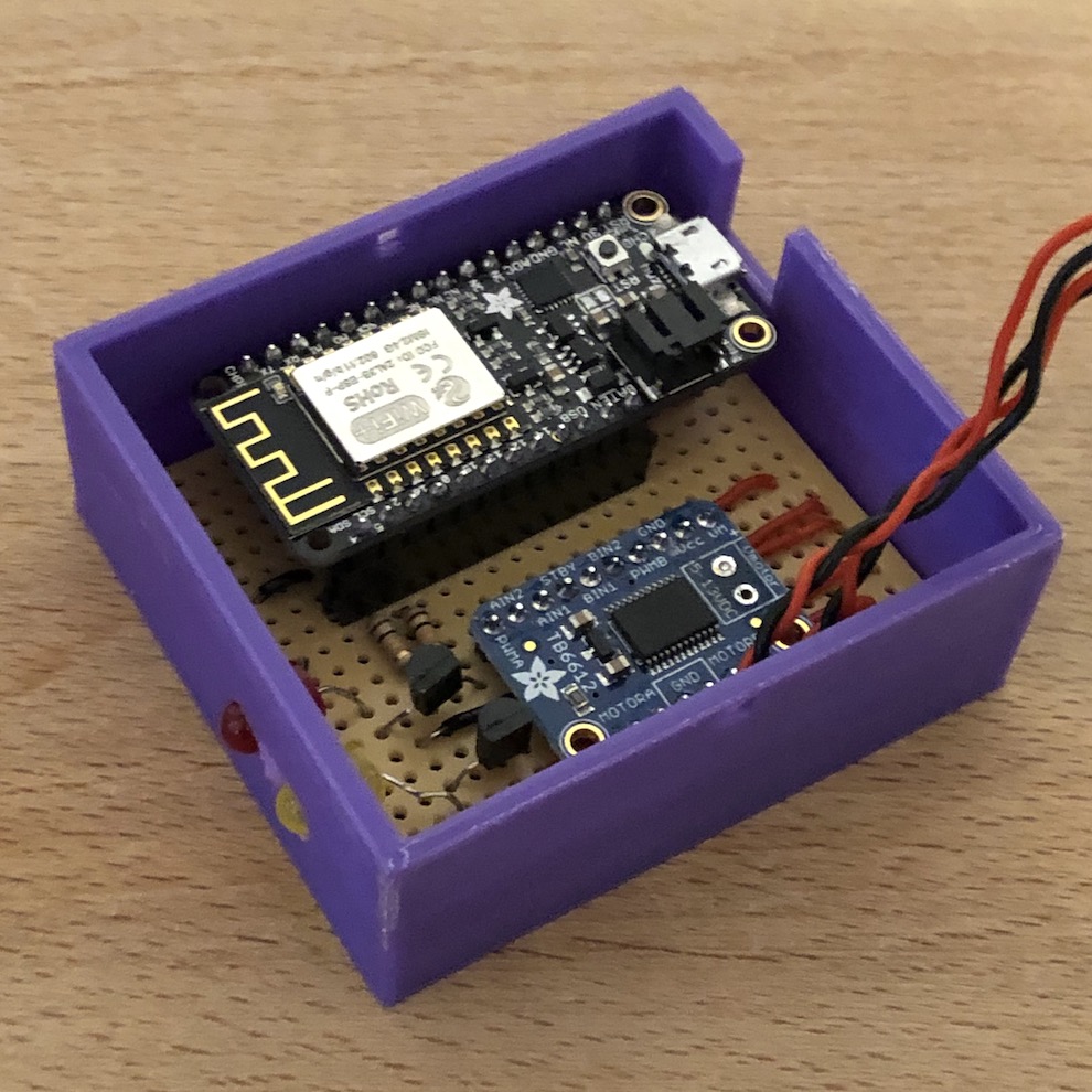
Finally, I velcroed it in place, tidied up the cables and put the teapots (I have quite a few for some reason) back in the cupboard.
Scheduling
All I really wanted was to be able to program my heating with more complex timers than was possible with the analogue timer alone. So, with all the hardware built and installed I turned to the matter of actually using it to control the heating.
As the heating can easily be toggled by writing a value into an Adafruit data feed, the scheduling does not need to be baked into the device – instead can be powered by some service.
The simplest way of getting a schedule going was to use IFTTT – creating an applet that uses the clock trigger and Adafruit IO connection to write a “1” or “0” into the feed when it should turn on or off.
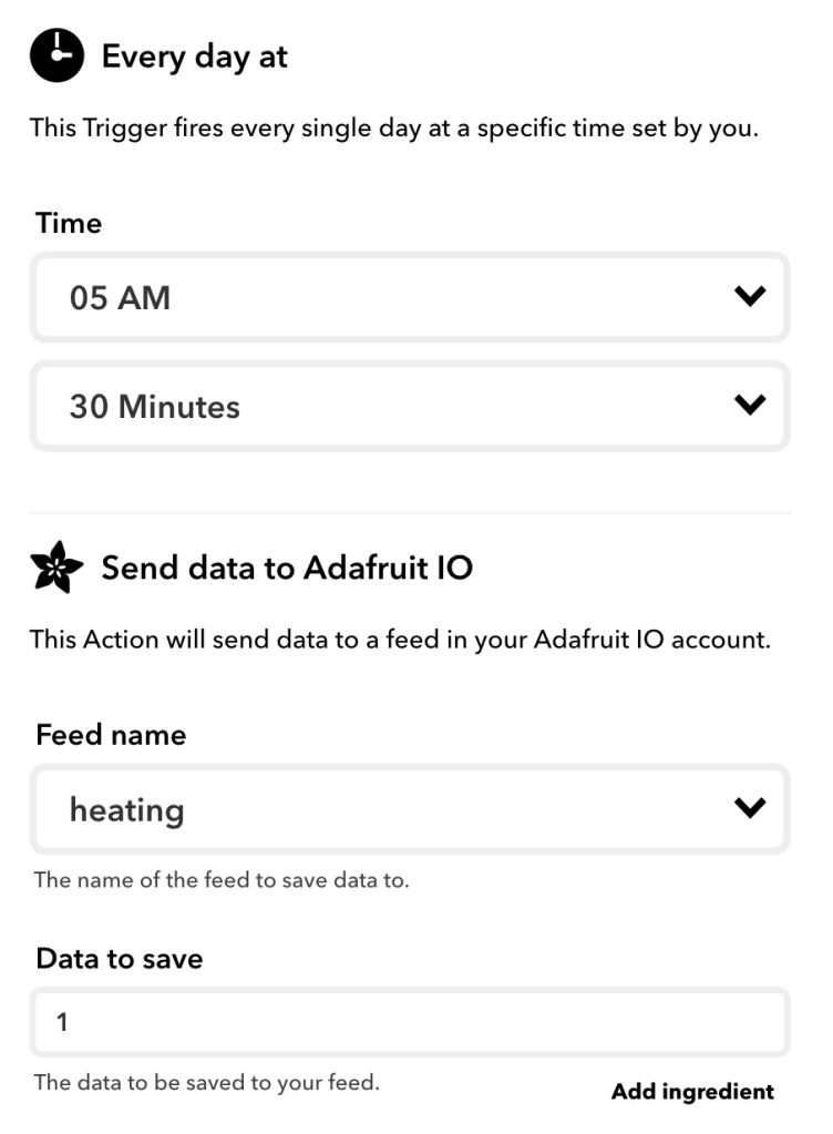
This works pretty well, but it has some issues. Firstly, IFTTT’s clock trigger is really crude – it doesn’t let you have daily tasks run only on certain days of the week. Also creating the Applets is a real pain because each on / off action needs to be created individually. For example, I wanted to suspend the schedule for a while, I’d need to edit each of them individually.
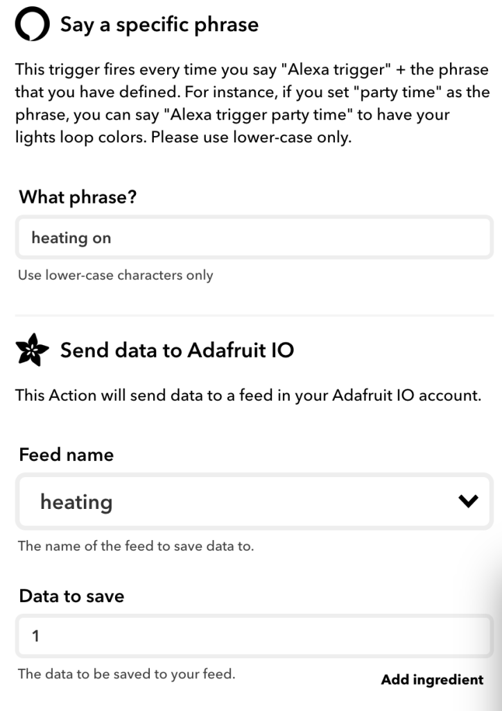
Alexa Voice Control
Obviously no smart heating would be complete without being able to use a voice assistant. That was also easily done with IFTTT using the Alexa connector:
What Next?
I’m very pleased with what I’ve got so far, but this will continue to be a living project that I’ll fiddle with over time. Here are some of the things I’m considering:
- Deep sleep – The ESP8266 supports a deep sleep mode where you can suspend execution and achieve very low power draw. It would be nice to make use of that. This would mean disconnecting the WiFi, so perhaps I could periodically wake it up and sync a schedule to run on-device.
- Programming – As discussed above, programming via IFTTT is crude. I want to build something better. I think I’ll ultimately end up building something custom that lets me create more complex programs possibly based around Azure Logic Apps.
- Alexa skill – “Alexa, trigger heating on” isn’t very catchy. It would be good to create a proper smart home skill so I could use “Alexa, turn on the heating”
- Better installation – The 3D printed “table” it sits on works well, but takes a lot of room. To make room for it, I literally removed one of my many teapots that now just sits on the counter. I can do better.
- Persistent storage – Currently if there is a power outage and an on/off trigger happens, the device will miss it and get out of sync – so it turns on every time it should turn off, and vise versa. Some kind of persistent storage of the current state, or at least making use of the Feather’s battery backup abilities, would help with this,
Feedback
I hope this was interesting (or useful somehow?) to you. I had a lot of fun figuring it all out. Let me know what you think in the comments or on Twitter.
Shutout to Holly who proofed this for me. Without her imput this would have been a much less concise read:


Nice work.
LikeLike
Hi. Nice work.
I love the 3D part
You may look into the Tasmota project which a nice firmware for Esp8266 based devices. Will provide 16 timers with day selection, rules for basic automation, MQTT for home automation or AIO integration.
All best
LikeLike
Ooo, that is interesting. Will definitely take a look, thanks 😀
LikeLike
You said: “Currently if there is a power outage and an on/off trigger happens, the device will miss it and get out of sync”. Is there any way you can ‘look at’ or take a signal from some element of the heating system or heating controller to determine what the system is actually doing? That would eliminate the uncertainty.
LikeLike
Yeah that’s a good idea- technically I could use a relay in the circuit being switched by the timer and use that as an input into the 8266, but I don’t really want to mess with the existing high voltage system. I wondered if a Hall effect sensor might be able to detect the current in the output cable when on and do a similar job.
LikeLike
Or perhaps an ESP-32 CAM or similar, looking at something on the controller which might indicate the ON/OFF state of the heating? I have no experience of the ESP-32 CAM, but it looks straightforward to use (!)
More to learn…
LikeLike
Ooo, ESP-32 cam does look interesting, might even be useful in some other projects too 😀
LikeLike
I understand the state is 100% determined by your wheel position.
So a Reed switch, micro switch, IR detector,… Could help to confirm the current position of the wheel at boot time.
LikeLike
You’re right, good point. I’ll have to look I to doing a V2 version 🙂
LikeLike
Hi Andy, well done in your efforts so far you have achieved a lot! I am in the UK, a heating engineer and a landlord! I wish you were a tenant in one of my properties, with your interest and determination I would let you do a proper upgrade on that dinosaur of a heating control.
Some one has mentioned Tasmota which is very good, there is also ESPHome and ESPurna. As a control system have a look at HomeAssistant (HA), it can run on a Raspberry PI and will provide all the control, and more, that you want. In conjunction with HA, and on the raspberry Pi, you can run MQTT, node-RED and loads of other software for control graphing etc. You do not have to use a raspi Pi either, I personally use a low end INTEL NUC. For control also have a look at BLYNK.
If you can access either live or neutral wire going to the heating you can use a PZEM-004T current sensor to detect the current when the heating is on, this uses a non invasive current transformer(CT) to measure current.
NB you have to pass either the live or neutral conductor through the CT but not both. However, you do not need to cut the conductor as the are Ct’s that open up to fit over the conductor and once in place they are closed again.
To detect where your actuator is you could glue a small magnet(s) to your stepper motor spindle and detect its position with a ‘hall’ sensor. You could add to sensors and two magnets 90° apart and create an encoder.
Lots of options! Sorry about the long post but I wanted to share some options. I love the 3D printing, I’ve got a machine but not used it yet. BTW have a look at Wemos D1 Mini controllers way cheaper than the ‘feather’.
Good luck
LikeLike
Hi Bob, glad you enjoyed my write up. There’s lots of great stuff to try out here – I’m particularly interested in your tip about the PZEM-004T, this looks like it would be a simple way know if the heating is running… Wondering if there’s anything else cool I could do with it in other projects, too.
I’m pretty new to the ESP family, still learning what I can do with it. I’ll need to take some time to investigate some of the home automation firmwares for it – it really looks like I’ve only scratched to surface so far :).
I’d switched to using an Adafruit breakout board for the ESP8266 for some other projects to save on the cost of the Feather (and get the physical size down a bit) but these need programming with an external FTDI->USB cable and are a fiddle to but into programming mode by holding down keys, so I’ll be taking a look at the Wemos D1, which looks to be about the same size, cheaper and has USB.
Thanks for the tips 🙂
LikeLike