This post is for information only. It is not a guide. Do not try this yourself. If you ask for help, I will not be able to give it.
Before the pandemic, when we started working from home, I used to make coffee a number of different ways, depending how I felt. I liked to experiment – sometimes I would use a V60, others a French Press, coffee syphon or espresso machine. This worked well on the weekends when I had time to experiment a little. However, when you need to grab a quick coffee between meetings, it turned into a real faff; there’s just no matching the convenience (if not the quality) of the office coffee machine.
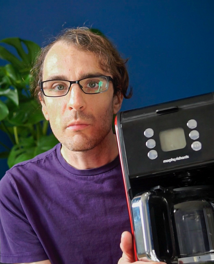
My solution here was to pick up a Morphy Richards Verve filter coffee maker that I could leave running while I went about my work and come back to when it was done. I was really surprised with this machine, I was expecting to sacrifice a lot of quality for convenience, but with a little fine tuning on ground size and water quantity, its capable of producing some very drinkable coffee.
Occasionally, though, I would get it brewing and forget to go back to collect the drink, leaving it going stale on the hot plate so I decided to see if I could connect it to my network for notifications and control.
My requirements were:
- At bare minimum I wanted to get a push notification on my phone / watch when a brew was finished
- As a stretch goal I wanted to be able to set the machine up with grounds and water in advance and remotely start it from my desk.
The Teardown
Electricity is dangerous! Disassembling appliances can lead to an electric shock, even if they are unplugged. This post is provided for information only, not as a guide. I take no responsibility if you hurt yourself or damage anything. DO NOT TRY THIS YOURSELF.
The first step was to pull the machine apart and see how it worked so that I could form a plan. The bottom panel unscrewed easily using a security bit, from there the decorative side panels could be unscrewed and slid off. This allowed me to hinge forward the display and control panel to get a good look.
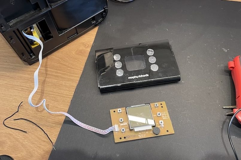
After some probing with a multi-meter, what I learned is that the coffee machine is controlled by a microcontroller on the top board, with the buttons and screen. This communicates with a second board at the bottom of the machine, which handles the high voltage switching. This means that I could safely hack away at the top board to gain full control without having to deal with mains voltage.
I did some bench testing on a breadboard and discovered that I could easily trigger a button press by bridging them to 0V. Next, I needed to find a way of determining the state of the machine. I found that I could easily determine if the element was active (meaning either brewing or keep warm) by testing if the power LED was high to 3.3V. Similarly, I could detect when the machine beeps by testing for 3.3V there.
This meant that I could build a simple state machine in software to detect the events of interest:
- Beep while hotplate off:
Ignore - Hot plate turns on: Switch to
Brewingstate - Beep while Hot plate on: Switch to
KeepWarmstate - Hot plate off while in Brewing or KeepWarm state: Return to
Standby
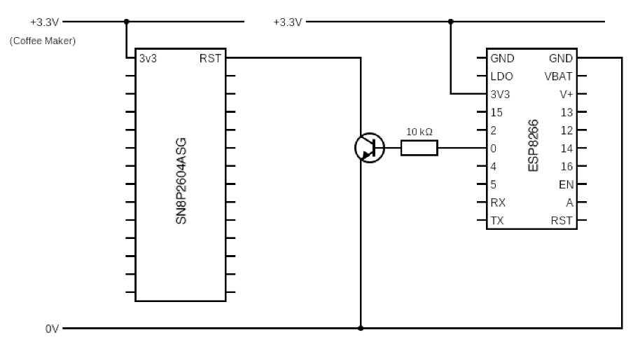
So, If I was detecting events to inform state, this leaves one remaining question: How can I be sure of the correct starting state? A quick search for the datasheet of the microcontroller used by the machine revealed that pulling pin 28 low would reset the controller. As the entire machine is driven by the top board, this had the effect of turning off the element, resetting the clock and setting the brew state to default.
The Plan
The plan was simple, use an ESP8266 to read the values of the element and buzzer, and control all machine buttons as well as forcibly reset the machines controller. On start-up, the ESP8266 could force reset the controller and would have all required control to set the brew strength, turn keep warm on or off, start / stop a brew and even set the clock if wanted.
To press a button, I can pull the button to 0V though a transistor, switched by a GPIO output of the ESP8266.

The same approach can be used to pull the reset pin low for the coffee machine controller.
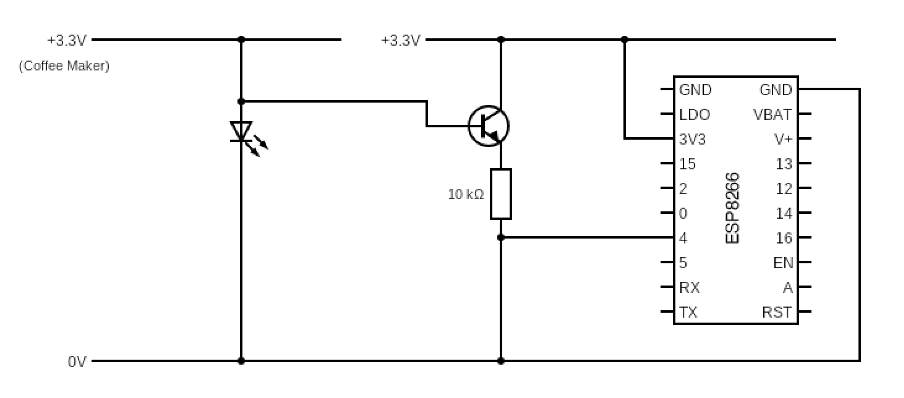
To detect either the LED or buzzer, I can pull a GPIO input high on the ES8266 through a transistor, switched by the feed to the LED/buzzer.
Hardware
I opted to use an Adafruit Huzzah ESP8266 breakout board as my controller and build out the supporting circuitry described above using Veroboard. There was a little void in the side of the machine, so I cut the board to size and hot glued it into that space, running cables through to the back of the control board.

Unfortunately, the 5V power supply from the coffee machine didn’t seem to be powerful enough to power the ESP8266 and caused the coffee maker to shut down. While I would have loved this to be an entirely integral solution, I decided to run a USB cable out the back of the machine to power my modifications. I used a Dremel to cut some channels in the plastic casing to route the cable out.
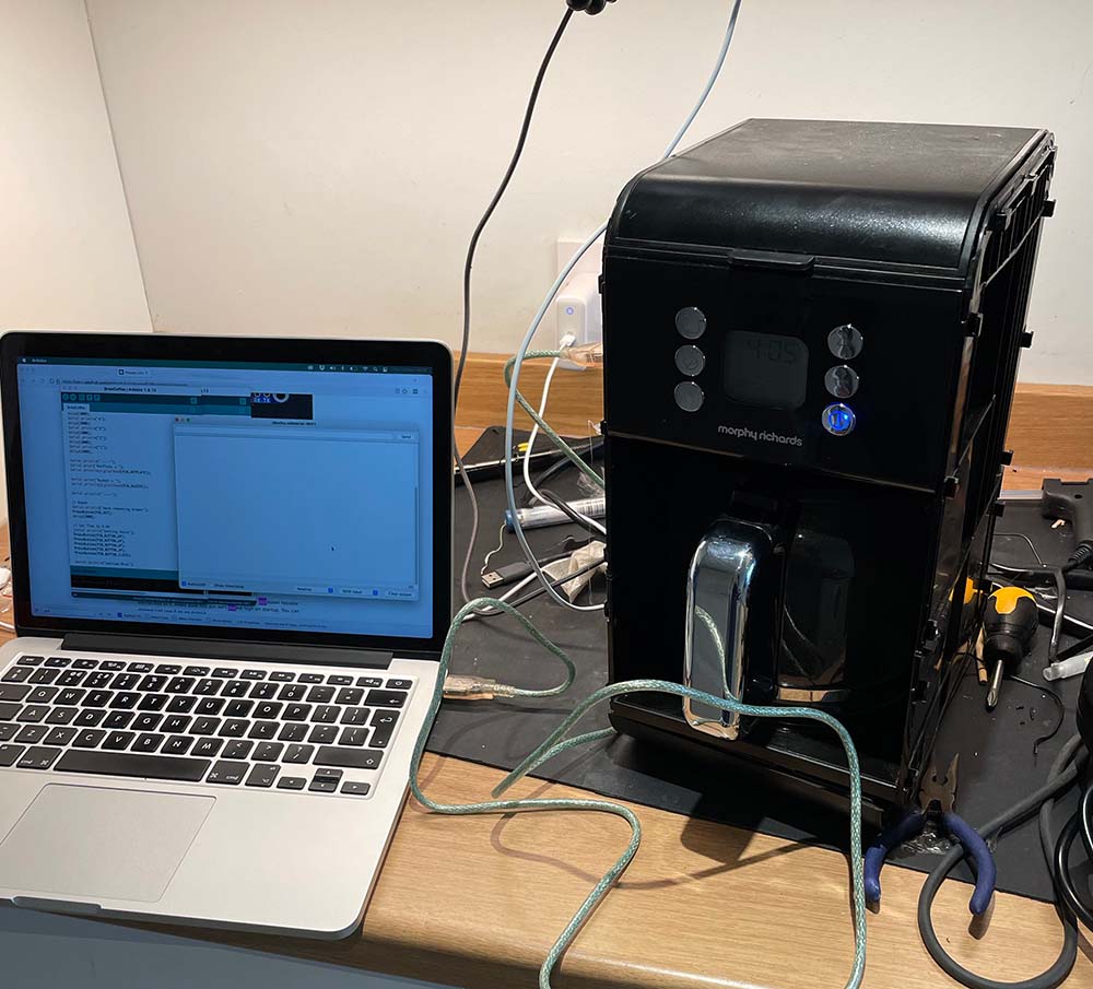
Software
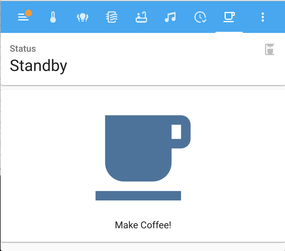
I wrote the software using the Arduino IDE. I made a coffee machine class to continually scan the inputs events and determine the state. I wanted to present this device to Home Assistant, so I could create dashboard buttons to start brews and automations to send alerts. To achieve this, I used MQTT auto-discovery for which, this GitHub project by Sören Beye, was a massive help in getting that working. The software I wrote is on my GitHub here.
In Home Assistant I created automations to send me notifications when the machine moves from the Brewing to KeepWarm state and if the machine spends too long in the KeepWarm state. I created a button that wrote a value to the command feed to start brewing. The Home Assistant Config is in this Gist.
Lessons Learned & Why My Socks Are Wet
As ever, this was a massive learning experience. I made some errors along the way and had to work around them or think on my feet. Here’s a run-down of some of the issues:
Don’t pull GPIO 0 low! …Or GPIO 15 high
While building out the hardware, I had written some test software to the ESP that allowed me to verify my work as I went along and it because apparent my code was no longer booting. I realised that if you start the board pulling either GPIO 0 low or GPIO 15 high it will enter programming mode. Both of which I had done. I was able to work around the issue with GPIO 15 by adding a resistor, however I was not able to fix the issue with 0 without starting again, so I decided to sacrifice control of one of the six buttons. I picked down, because I don’t actually ever need to press it.
Remember your resistors.
I missed some resistors when soldering the board together and spent quite a while tracking down shorts.
Water leaks
While cutting a channel for the USB cable, I cut right into the water tank. Now if you try and make more than one cup of coffee, the water pours out of the side, really helpfully into the electrics. I learned this for the first time was it flooded my kitchen and poured water on to the floor.
TokTok
You can watch the time lapse of this project, and my other smart home Adventures on TikTok.
Final Thoughts
I hope this was interesting and maybe you even learned something? I certainly learned a whole lot along the way, and it was a lot of (frustrating) fun troubleshooting the problems. Let me know what you think in the comments or on Twitter.

What an innovative approach to making coffee smarter! Andy’s modifications transform a standard coffee machine into a high-tech appliance, enhancing convenience and control.
LikeLike